I am a newcomer in Corry and I do my first analysis.
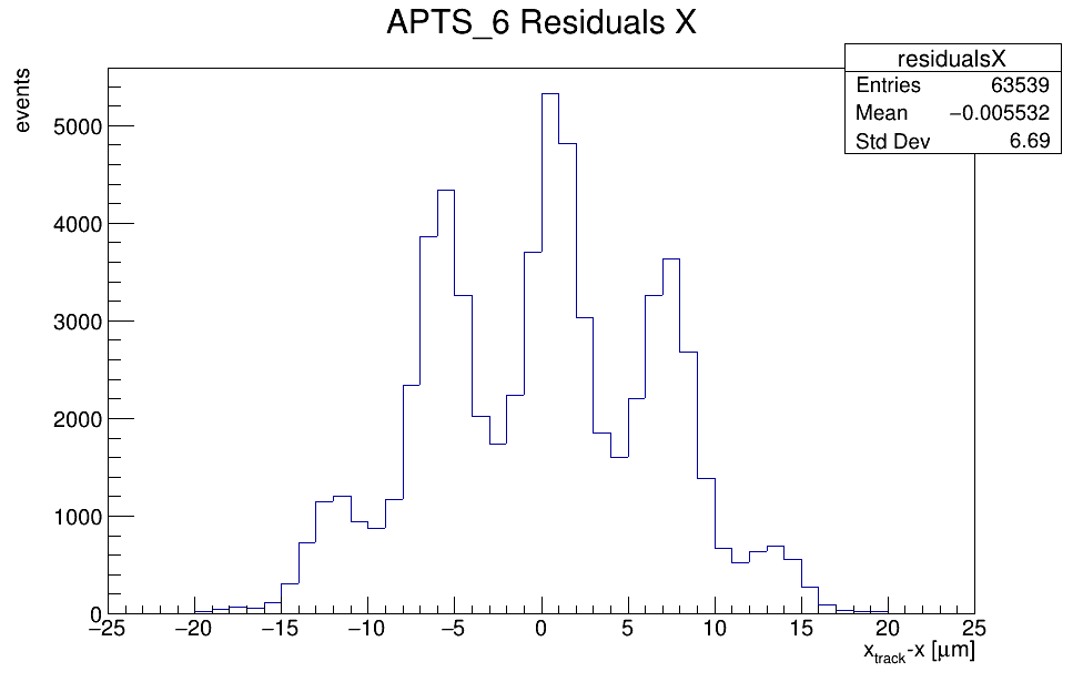
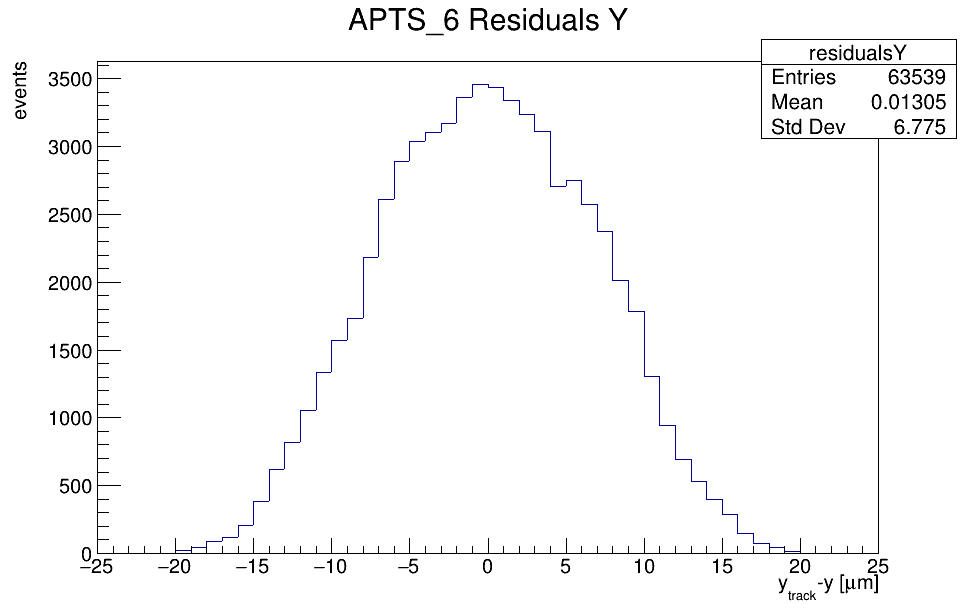
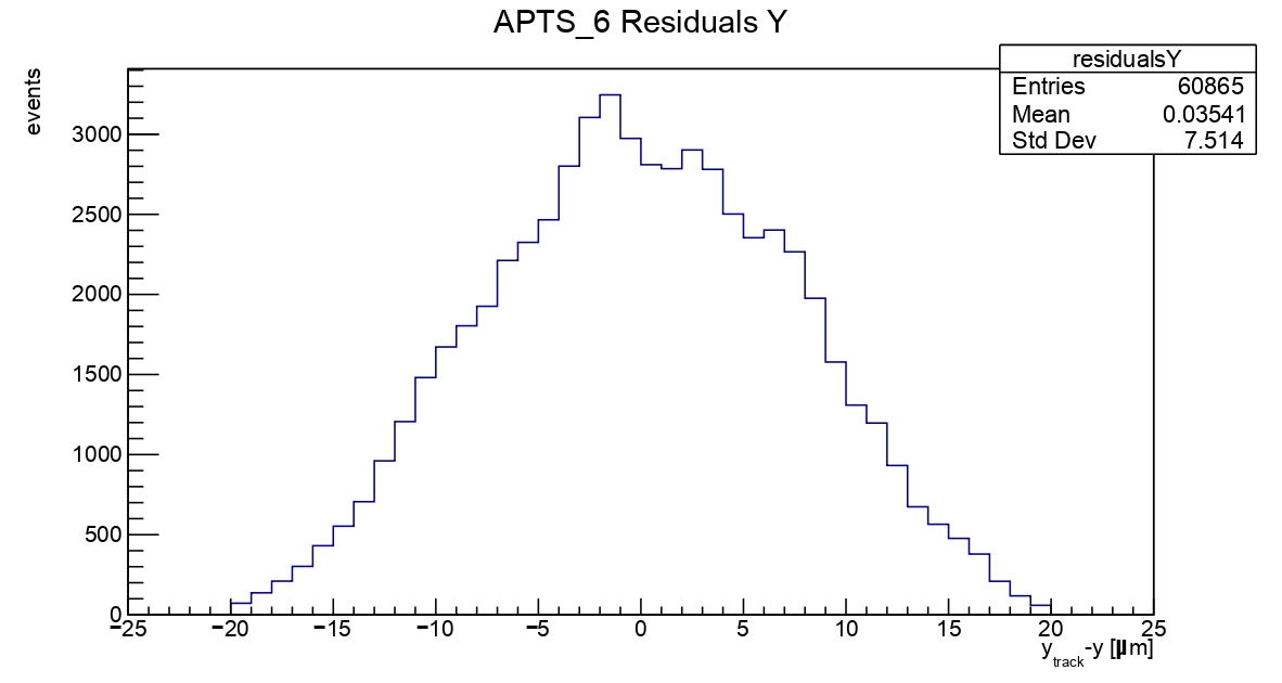
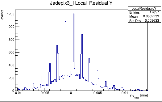
I observe spikes on the residual plot for DUT at the X axis. Note that the same plot but for the Y axis looks as expected. My colleagues told me that these spikes should not be observed in the DUT residual plots.
Let me give some details: our telescope consists of 6 ALPIDE planes and 1 APTS chip (in the middle), which plays the role of DUT. In addition, APTS plays the role of the trigger. The electron beam was utilized with an energy of 855 MeV. The APTS chip has a much smaller size than the ALPIDE sensor. To improve the DUT alignment, we specify the region of interest (ROI) for the ALPIDE planes. ROI is specified based on the ALPIDE hit maps. Number of events: 75k.
Telescope alignment
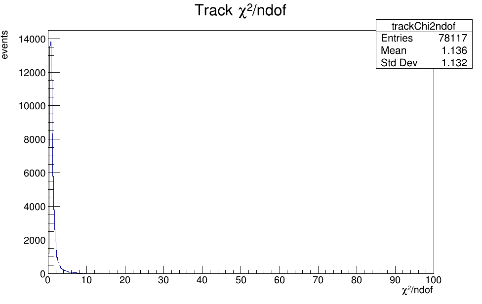
The residual plots for ALPIDE planes also contain spikes (see CERNBox). However, I was told that it is ok, but I do not know why. The tracking looks good to me. I used spatial_cut_abs = 75um,75um. Fit model: GBL. I tried to perform tracking with and without ROI. Nothing changed.
DUT alignment
After the telescope alignment, I moved to the DUT alignment. The DUT was aligned along the X, Y axes (Z is fixed), and rotation was enabled only around the Z axis. I also tried to enable rotations around all axes, however, it did not help. [DUTAssociation] was done for spatial_cut_abs = 20 um,20um (size of APTS pixel pitch). Additionally, I studied the DUT alignment using tracks within ROI and all reconstructed tracks. It did not bring any improvements.
In the repository, you can find the config files and other figures: CERNBox
Could you suggest what can be changed/tested in this situation?
P.S.: does the [Tracking4D] module care about particle type?
Hi Artem,
I have seen residuals like this before. Usually they suggest a correlation between the hit positions on the individual detectors. This is typically caused by e.g. small distances between planes, small angular divergence of the beam, small beam diameters, or another combination of geometrical properties. If this affects your reference system, I see no reason why it should not affect the sensor you are studying. I would recommend you discuss this with your supervisors and try to understand why this could happen with your setup. I would be surprised if this was an effect introduced by corry.
Regrading, your last question: There is no parameter like particle type mentioned in the corry documentation, and as far as I know, the scattering angles (which are derived in the GBL track model) depend on momentum, particle charge and material budget.
Thank you so much for your comment! I will discuss the suggested points with my colleagues.
For my clarification: according to the official manual, the [Tracking4D] module does not have a setting, which is in charge of the specification of particle charge. Does it mean that for the [Tracking4D] there is no difference between proton/pion/electron beams with the same momenta?
Thank you for the link! It is interesting. The formula for scattering theta angle contains in the denominator beta factor, which is a fraction of particle velocity in terms of speed of light. In the code, I suppose the beta factor is taken to be 1.0. For an 855 MeV electron beam, it is true, but for non-relativistic protons not. However, this question should not be addressed to you, unless you are a developer of the GBL model
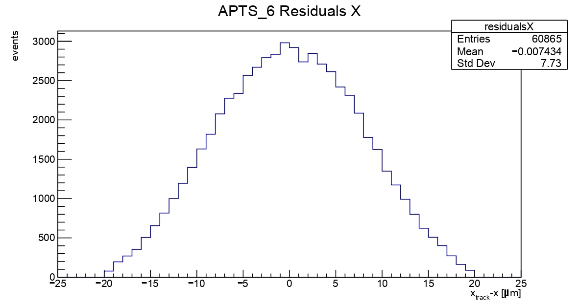
Regarding the issue with residuals, you were right. It seems that the telescope geometry should be specified more precisely. A small shift in the Z-coordinate of the DUT leads to such improvements.
I would also like to have a particle type definition in tracking
I opened an issue a while ago: Adding particle type and impact on eg: scattering angle with GBL (#179) · Issues · Corryvreckan / Corryvreckan · GitLab
Basically, we can have some particle definitions and helper functions to calculate the beta from the momentum and particle type and then inserting it in the Highland formula that Finn mentioned.
If there is a preferred way for implementing (since my original idea was kindly vetoed ), can somebody suggest it on the issue?
Do you see these residuals on the DUT plane or tracking planes?
In my case, I saw a similar sharp shape of the residuals on some tracking planes. I had a discussion with my colleagues and they said that more important is the distribution of residuals on the DUT plane. i.e. if you see good residuals on the DUT you could ignore residuals on the tracking planes. Please, correct me if I am wrong.
I had an issue with the DUT residuals. What I did:
I shifted the DUT z coordinate ± 10 mm from the nominal point at 60 mm with the step 1 mm, Z coordination of the tracking planes was untouched. As a result, I got 20 analyses with different Z positions of the DUT plane
For each analysis, I checked the DUT residuals. I looked for the residuals with the expected single-peak shape around 0. If I had several analyses that satisfied this criterion, I looked among them for the residuals with the smallest width. At this stage, I got a new Z position, for instance, Z = 58 mm;
I repeated analyses but the nominal point was Z = 58 mm and I added variation ± 1 mm with step 0.1 mm (finer tuning). Finally, I got the value of Zdut = 57.6 mm, which I used in my analysis.
It helped in my case
Typically, a test beam telescope has planes, which are equidistantly separated (at least in our setups, planes are parallel). From my colleagues, I learned that in our setup, the DUT plane was not perfectly located in the middle between two nearby tracking planes. Therefore, it was an additional motivation for the DUT z coordinate scan.
Hi,
Thank you for your patient replies and advice. I see these odd residuals on some tracking planes and the DUT has gaussian distributions of residuals (for gbl). For straightline model, the residuals look normal but have larger resolutions. Our telescope is supported by fixed skeleton and the distance between every plane is 26mm. Maybe this is the reason for the odd residuals. Thanks again.