Dear experts,
I have a new problem to submit to you…
I am testing a new pixel detector module as DUT that consists of 4 ROCs and a single sensor.
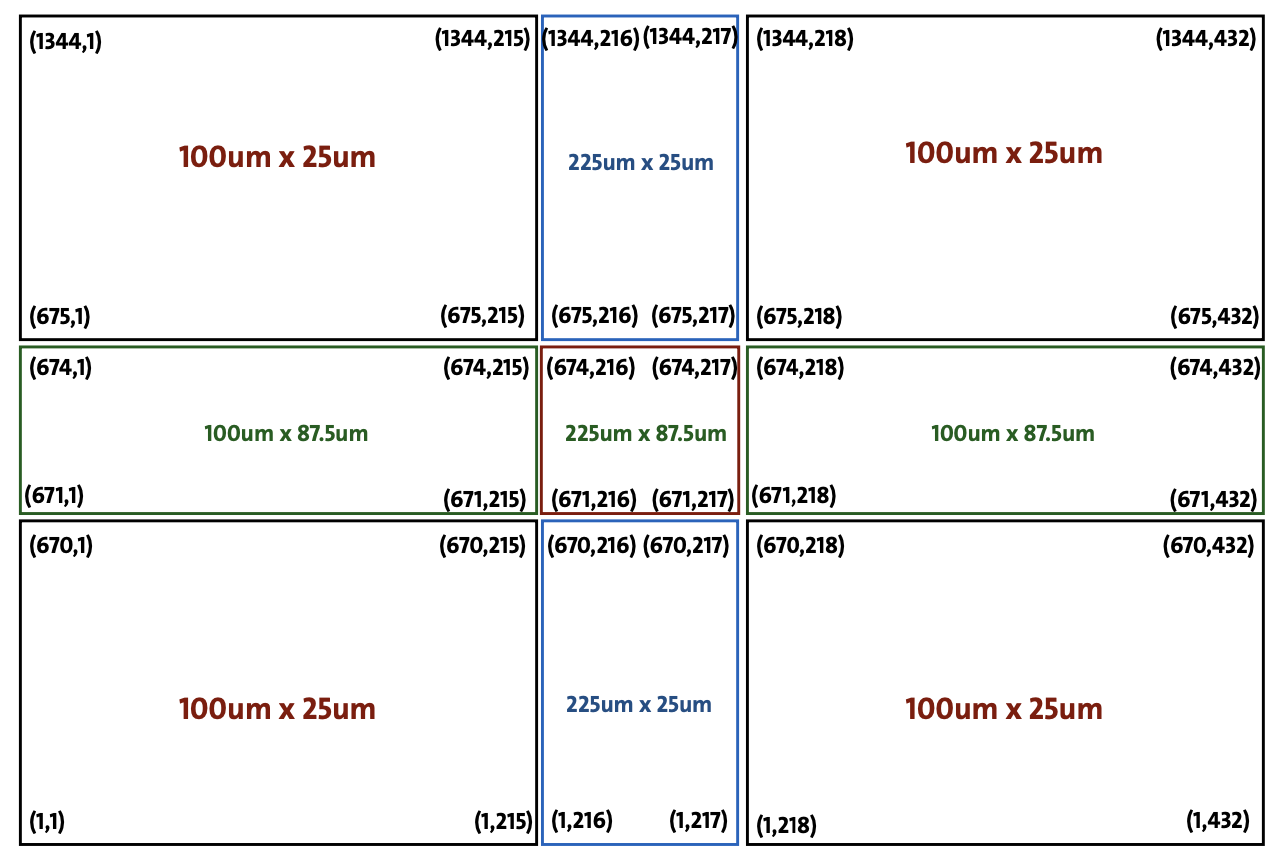
Unfortunately, this sensor has 4 different types of pixels:
“standard” 25x100 um2
“pixels in the columns where two ROCs are joined” 25x225 um2
“pixels in the rows where two ROCs meet” 87.5 x 100 um2
“4 central pixels” 87.5 x 225 um2
On page 28 of the manual, it is stated that currently, the supported geometries are only:
cartesian mode = all rectangular pixels with the same pixel pitch
big_pixels mode = where you can provide a list of rows and columns with pixels that are double the size of the others.
Hexagonal pixels (not my case)
When I made a first trial without the big pixel option, I clearly got strange residual distributions, and the alignment was not good. So I tried adding the big pixels, but still, since they are not simply double the size of the others but a more specific measurement, the situation improved slightly but didn’t fully resolve.
Furthermore, I cannot observe any correlation in the “local” coordinates but only in the “global” ones. Moreover, Corry provides a warning in the analysis, saying that using big_pixels in the DUT can lead to undesired results in the analysis.
Therefore, I wanted to ask if there is an already implemented way to accommodate my needs in the DUT, what the problem of using the “big_pixels” geometry in the DUT is, and why there is a warning. Additionally, in case I need to implement a new “big_pixel” myself, where do you suggest starting, and which modules should I modify to remain compatible with your release?
We have similar issues with ATLAS ITk endcap sensors, which have rows with different pitches. We current analyses it as a single row detector, not very friendly (analyse same data multiple times and so on).
My favoured solution (long term) is to split the Detector class in two: a Detector is a specific instance of a sensor design, so a Detector has a position, orientation, type, … as well a a pointer to a sensor type.
A design inherits from a pure virtual base class which guarantees it has conversions from row/col to position and vice-versa, lists of neighbour diodes, etc. - everything that is identical for all similar detectors. Then sensor designs would inherit from this, and implement the methods. E.g. Mimosa26 would be a “SquareSensor” with very simple calculation of local position; a Mimosa26Sensor would be a SquareSensor with pitch and number of rows = number of columns.
Obviously your sensors would be more difficult to implement.
Apologies for the late reply, just back from holidays.
The conservative option would be, if acceptable, to analyse the different sectors individually.
This is due to some histograms that might not support BigPixelDetector by having for example a fixed pixel size in the binning.
I think the BigPixelDetetcor is a good starting point, which you can try to generalize. But this will have an impact on the histograms in essentially all analysis modules (binning will have to change)
Your suggestion might be a good path for the, as said, long-term improvements. Implementing this in the core of Corry is also feasible. but automatically scaling/splitting all produced plots and the edges between different pixel sizes etc might be difficult.
Hi @lhuth,
thanks for the reply.
Unfortunately, I’m afraid the idea of analyzing multiple times might not work, but maybe I’m mistaken…
Let me explain it better: Here you’ll find the image with the dimensions and the number of columns and rows of our sensor.
I’m not sure how the alignment of Corry works, but if it uses millimeters and sensor coordinates, how can I align assuming that the entire sensor is, for example, 100x25 pixels? After the columns with the big pixels (216 and 217), I expect the alignment to no longer be correct but to have an offset, and the same holds true if I were to consider a DUT with only large pixels. Or am I mistaken?
Furthermore, for the efficiency calculation, if the reconstructed track and the center of gravity of the cluster are shifted due to the altered mapping, how can it yield a correct result?
The same applies to resolution and residuals, as masking the big pixels, for instance, would result in incomplete clusters.
first of all my apologies for ignoring that post - the forum is not sending notifications to me
One option to implement this would be a new pixel-detector class that takes care of all the different sub-matrices you have. Subpixel plots etc need to be defined for the different regions in that case. This can get rather complex…
Dear @lhuth together with Chin-Chia we think we manage to change accordingly the code.
I have created a new branch to try to keep the changes clear and we will try to ask a merge request as soon as we will be sure that everything works everywhere but maybe we will need your help for the integration in corry official repository.
Anyhow now we can align, use and analyse the data!