Odd-looking residuals telescope and DUT alignment

Dear experts,

We are relatively new to Corryvreckan and are running into issues with the alignment procedure for our test beam setup.

The setup consists of six MIMOSA 26 telescope planes and a single 1.3x1.3 mm2 LGAD sensor in the middle, i.e. three MIMOSA planes on either side of the sensor. Instead of actual test beam data, we are using simulated data generated by Allpix2 for a 5 GeV square beam of electrons (uniformly distributed) with sides of 1.35 mm which we load in via the FileReader module.

Issue regarding the alignment of the telescope

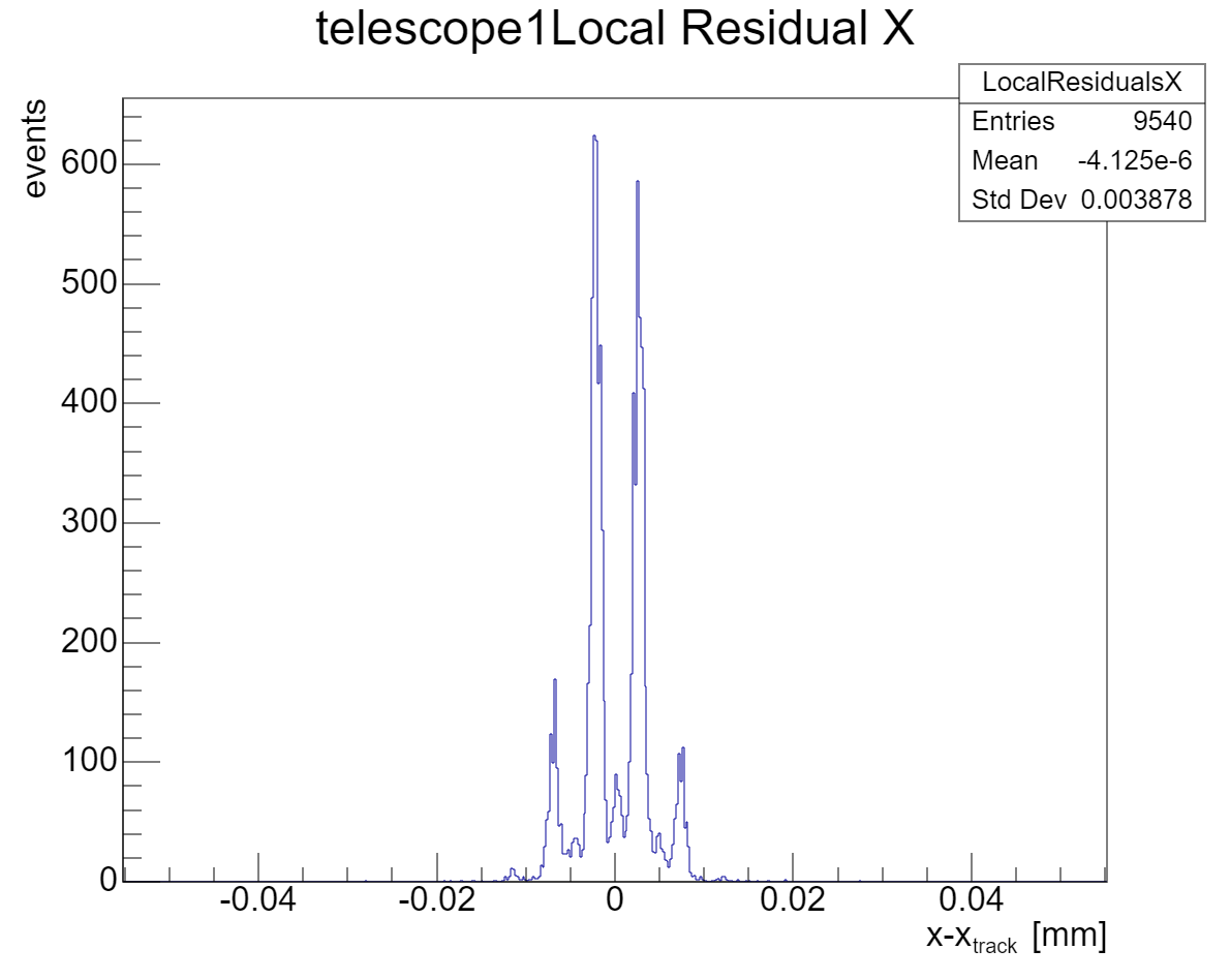
After one iteration of the Prealignment module for the telescope and three iterations of AlignmentTrackChi2 (decreasing the spatial_cut_abs for each iteration from 200 um, to 100 um, to 50 um), the residuals of telescope1 and telescope4 – the ones that are in the middle for the triplet of MIMOSA planes before and after the DUT – still display a ‘spiky’ pattern with roughly evenly spaced peaks. (See the picture below and the configs in the attachment.)

We were wondering if someone could explain
a) the cause of these patterns in the residual plots to us;
b) why they are only present in the plots for telescope plane 1 and 4; and
c) if this is something to worry about.

We have tried using different track reconstruction models (gbl is used for the image above, but we have also tried straightline), but the peaks show up regardless.

Issue regarding the alignment of the DUT

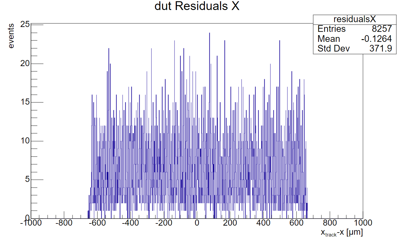
For aligning the DUT, we adopted a similar procedure using AlignmentDUTResidual and decreasing the spatial_cut_abs from 5 mm to 2.5 mm to 1.5 mm. The issue here is that we have no way of validating the alignment because the residuals, as expected, display a uniform distribution. Since our DUT only consists of one sensor and all clusters are reconstructed in the centre, the residuals simply show the distance between the interpolated track intercepts – that are uniformly distributed over the sensor - and the middle of the sensor.

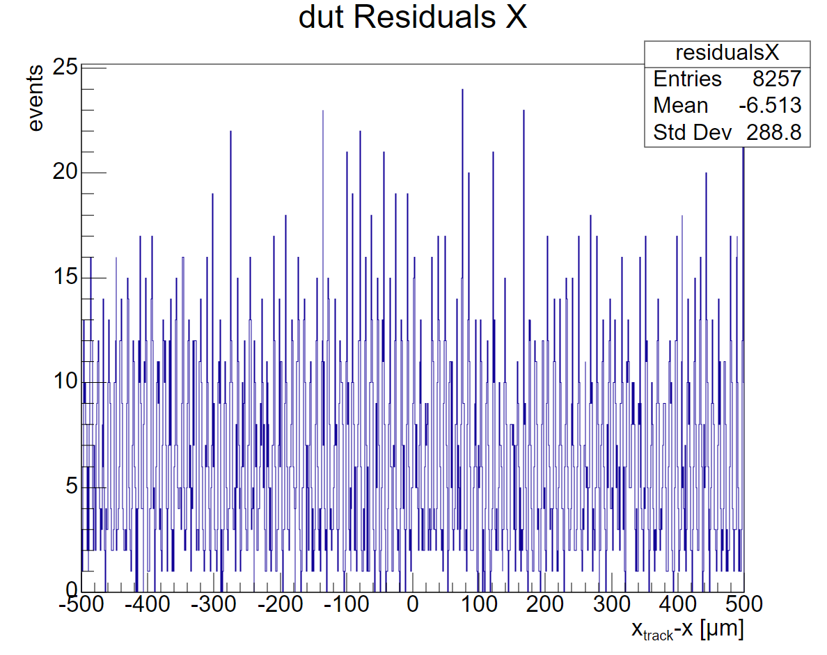
Our question is: is there an alternative way to validate the alignment of the DUT? We know for a fact that it is currently off because the position of the DUT provided by Corryvreckan differs about 8 um from the position of the DUT we have simulated our data with. Hence our interest in improving the alignment.

Thanks a lot in advance,
Robin & Andrea

DUT_alignment.conf (909 Bytes)
telescope_alignment.conf (884 Bytes)

Hi @rkan

  1. This is a well-known effect that stems from the fact that cluster locations on sensors are not necessarily smooth distributions but are binned by the pixels. I am - wildly - guessing that when preparing your simulations in Allpix Squared, you did not make use of the automatic misalignment feature. Hence all your sensors are perfectly aligned and your reconstruction produces artifacts owing to the fact that M26 sensors will only produce distinct cluster positions (single pixel: pixel center, two pixels: pixel edge). The result is the spikes you are observing.
    If you want to get around that, just introduce a slight misalignment in the simulation (check the manual for alignment_precision parameters here), perform an alignment in Corryvreckan and then look at your beautiful residuals. :slight_smile: With actual data and the M26 I do not expect this effect to appear, or at least not as pronounced as here.
  1. I would expect the algorithm to just work fine - but the histogram you are looking at does not cover your full DUT (just 1mm, while you claim 1.3mm pad width), so you likely need to change the range for the histogram to show you the outline. Having said that, the accuracy is probably not in the sub-um levels, but I presume that’s also not something you are aiming for.

Best,
Simon

Hello @simonspa,
Thank you for your quick reply!

  1. The explanation you provide is one that has come up several times before, but we are afraid that the issue we are facing is a bit more complex. We indeed did not make use of the automatic misalignment in Allpix2, but we manually misaligned the telescope planes using the actual positions of the planes obtained from test beam data (see the geometry we feed to Allpix2 in the attachment). With this extra knowledge, do you think the pattern we observe can still be attributed to this binned clustering of the M26 sensors, and, most importantly, is it a reason for concern? We are also still struggling to understand why this pattern, even if it is ‘harmless’, is only exhibited by telescope1 and telescope4.

  2. Good point! Below you can see the histogram for the residuals with extended axis range.


    What we understand from your reply is that it is not uncommon for the residuals of the DUT to look like this and that there is no need/no other way to improve the simulation than by looking at the residuals, which in this case – even with visible outline - do not give us much information. Do we interpret your answer correctly or are we missing something?

Thanks again,
Robin & Andrea

geometry_allpix2.conf (745 Bytes)

Hi Robin & Andrea,

1: a) As Simon said they are likely an artefact of the way your alignment is done. In all your geometries, there are no rotation around any axis provided. This is a simplification of reality - no sensor is perfectly glued on a PCB and placed without any rotation relative to the others of the telescope. If you do not allow for rotations in your telescope alignment, the spiky pattern will remain (of coarse also on the simulated data at the end).
b) The inner planes of each layer are most constraint on both sides. This causes the pattern to be more clear than for the outer most layers (0 and 5) which do only have a hit down/upstream and the ones where the DUT is in-between.

c) No as it should disappear after correcly applying the rotations, see a)

2:

I am not sure if I fully understood your point: Your gut residuals along x has a mean 0f -0.1264um, which is pretty precise for a 1.3mm single pad LGAD pad. The AnalysisDUT module also offers the 2D residual map, which should clearly reassemble the LGADs pad (maybe you are having curved edges, that you could check for?)

Cheers,
Lennart

Hi @lhuth ,

Thanks for the clarification. We had tried to allow for rotations in the alignment before - which did not have any effect - but only after reading your message we realised that we also had to allow for rotations when generating the Allpix2 data itself. Now the residuals of the inner planes look just fine!

Considering the alignment of the DUT: I think we were simply unaware of the fact that looking at the mean (instead of the standard deviation of the residuals/their shape) provides you with enough information to conclude whether the alignment was successful. According to your judgement, it was, which is all we wanted to know. Otherwise, we would have kept trying in vain to improve the alignment to reduce the 8 um deviation we observe between Corryvreckan and Allpix2.

Thank you both for your help!
Robin & Andrea